The Chassis & Mobility Subsystem (CAM)
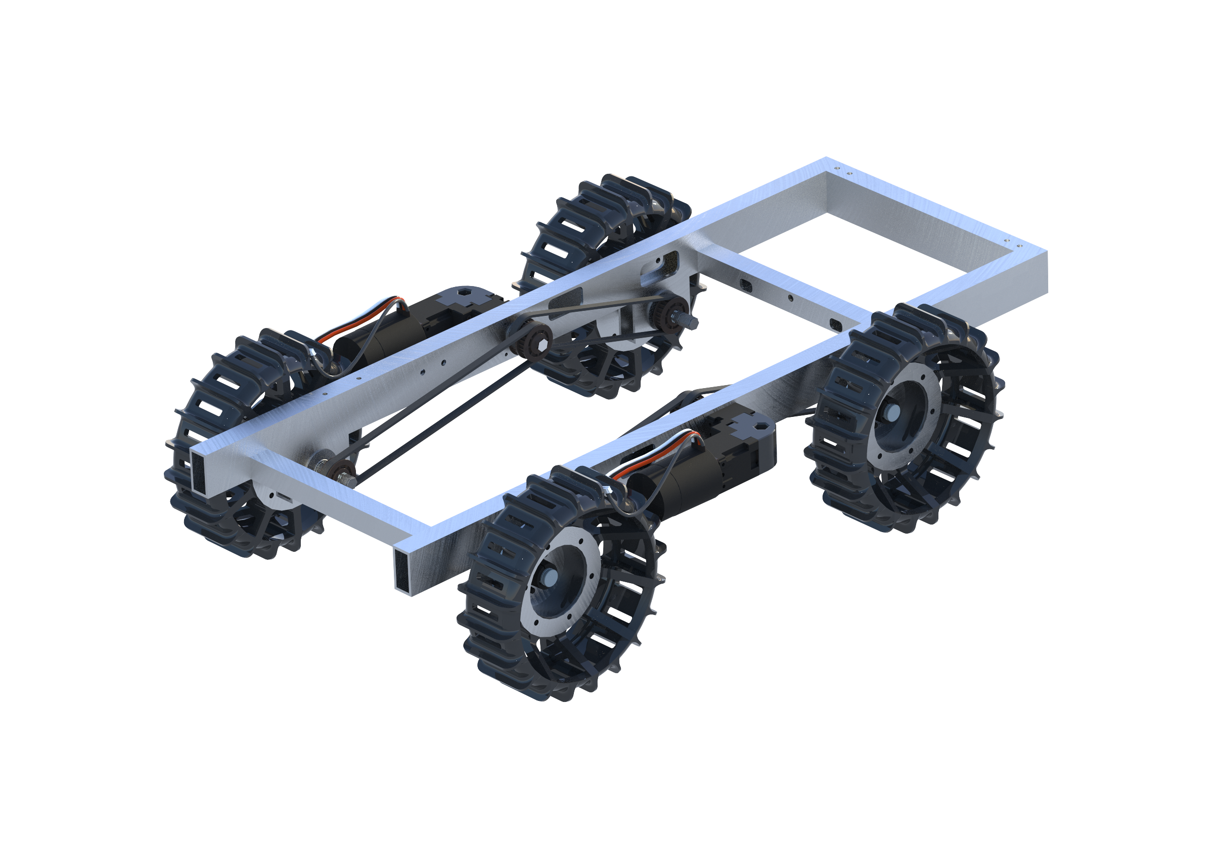
The Chassis & Drivetrain is in charge of
the design, manufacturing, and testing of the lunabotcs
chassis and drive train. We make sure that these two parts
of the rover fit within competition constraints as
requirements made by our team, that our designs are viable
as well as optimal for the competition and our CAD is up to
date and accurately represents what we have manufactured.
We use a combination of CAD and FEA to create a chassis that
fits our needs while also reducing the weight of the design
by removing unneeded material found in our FEA analysis. Our
drivetrain system is designed to reduce the number of motors
needed to drive the rover white being able to fit in the
limited build volume of the competition. Lastly, our wheels
are 3D printed to reduce weight but are designed optimally
to the extent that they can withstand 250lb of compressive
force. We are constantly looking for ways to reduce weight
while improving our structural integrity.
The Electrical Hardware & Data Acquisition Subsystem (EDAQ)

Our team is responsible for the coordination
and management of all the electrical devices and wiring on
the robot. We ensure that all crucial components such as the
drivetrain, excavation motors, hopper conveyor, and
actuation system are secured and receive the enough power
from the battery to operate at their optimal capacity. All
components are also linked together via communication wires
which will transfer sensor information to the brain of the
robot, the RoboRIO, and allow the Software and Communication
team to control the robot quickly and reliably in both
manual and autonomous mode. Every step is done properly and
multiple safety measures have been taken to protect both the
users and the robot from itself while in operation.
The Excavation Subsystem (EXC)
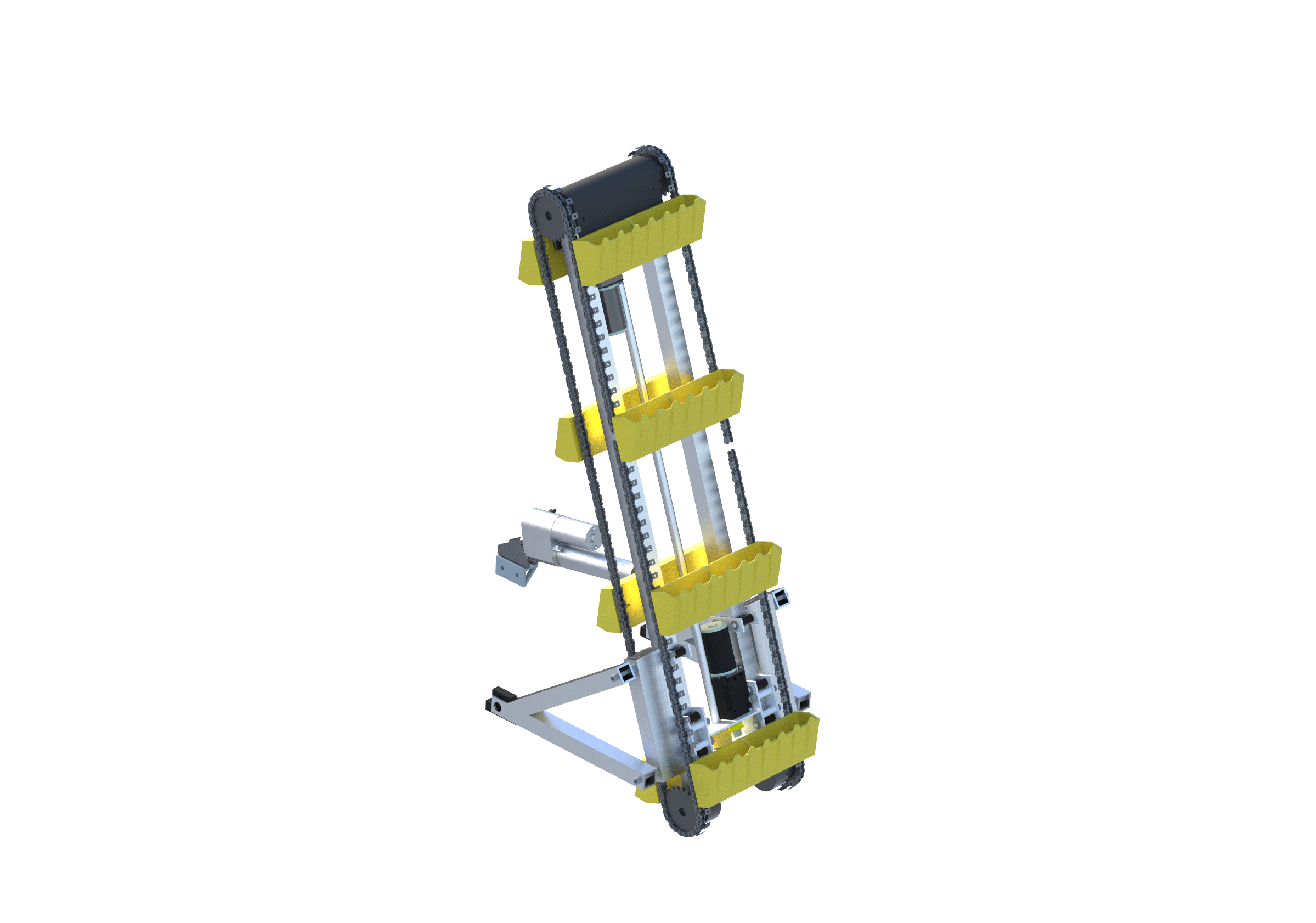
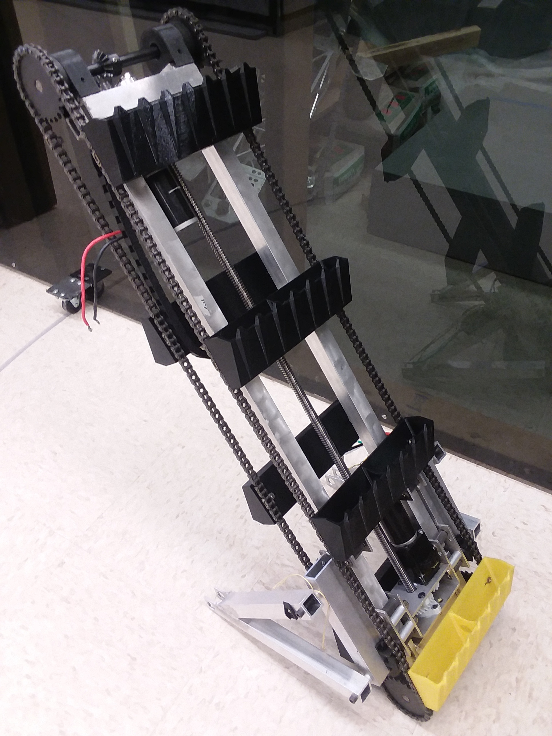
The Excavation sub-team handles the
design, optimization, construction, and testing of the
excavator for the Lunabotics robot. We make sure that our
system is able to mine the required amount of rocks and
regolith for the competition. The design of our system is
very compact and has several intricate mechanisms that work
together to activate, extend, and excavate material. Due to
the size constraints given by the rules, our robot must
start off in a compact form. The excavator starts off folded
up on top of the hopper and hopper conveyor. The arms the
excavator is attached to are able to pivot on bearings,
which allow the excavator to fold down into its active
position.
Our excavator uses a bucket ladder design with
eight buckets attached to a chain that is driven by a motor.
The buckets rotate around the frame on the chain. When the
bucket takes a scoop of material, it brings it up to the top
of the excavator and then dumps it into the hopper which is
positioned to catch the incoming rocks and regolith. In
order for the excavator to mine down deep enough to reach
the desired rocks, the excavator needs to be able to extend.
This extension is achieved by the use of an ACME rod and
nut. The carriage of the excavator houses a motor and
gearbox that drive a set of gears that rotate an ACME nut
around the acme rod. This nut is held in place by two thrust
bearings. The rotation of this nut facilitates the extension
of the excavator into the ground. When the excavator digs as
far as it can, it then uses the same mechanism to bring it
back to its ready position.
The Hopper & Material Handling Subsystem (HOP)
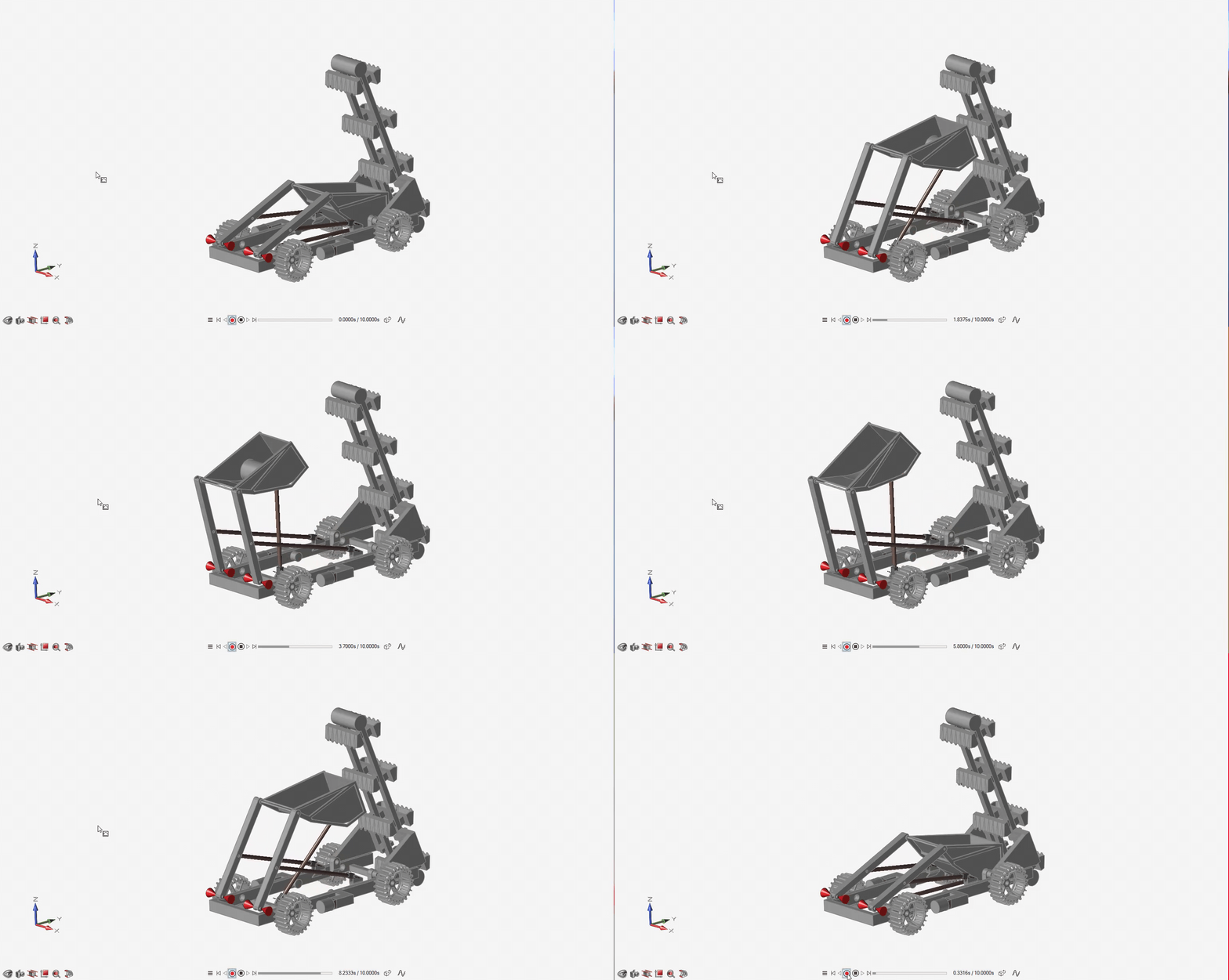
The Hopper and Material Handling sub-team
is in charge of designing the mechanisms to handle the
excavated material during transportation and deposit it at
the collection point, which is a sieve located on a wall of
the arena. We designed the Hopper System to be a single bucket
that can hold an entire kilogram of gravel in 1 duty cycle
of the robot and can deposit it through the use of 4-bar
linkages. To validate that the bucket frame, drive links,
and attachment points will not fail under competition loads
we conducted a comprehensive Finite Element Analysis on the
system. The results of our FEA allowed us to proceed further
with the linkage design. To off-load the material excavated,
the 2 linear actuators located on the frame of the robot
will extend lifting up the bucket in the air then the center
linear actuator will extend to tip the bucket. The final
details of our design are currently being worked out and the
manufacturing will begin shortly.
The Rover Autonomy & Networking Subsystem (RAN)

The Software & Communication Team was
created to have two major Spheres of influence on the
Lunabotics project, which, as the name suggests, are writing
Software for the Robot and controlling Communications
throughout the Control system. The Former Sphere involves
writing programs to control various actions around the robot
using, preferably, closed-loop methods such as extending the
excavator into the ground based on the input of an encoder
and limit switches. This is done primarily through the use
of the programming environment used in FRC, made by National
Instruments, and known as "LabVIEW." Other Programming
languages such as Python, C, and HTML are used for various
other portions. You can thank us for this lovely website.
When it comes to the competition, our subteam is the most
crucial, as the majority of points won during the 15 minutes
of operation are achieved through the use of automation.
The latter sphere of influence, the Communications aspect,
is achieved through the utilization of various electrical
components and programming methods such as a Raspberry Pi,
Wireless Access Point, and RoboRIO. This combination of
devices, languages, and connections makes communications one
of the more complex portions of the subteam and an ongoing
project to find the best way to send data to and from the
robot.
The System Integration Sub-Team (SYS)
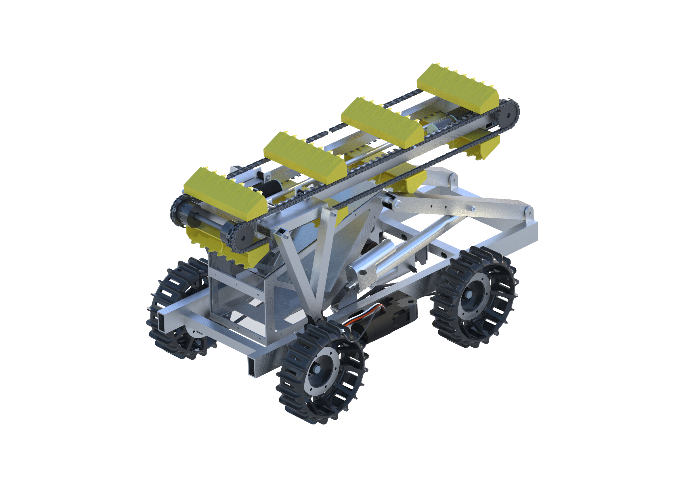
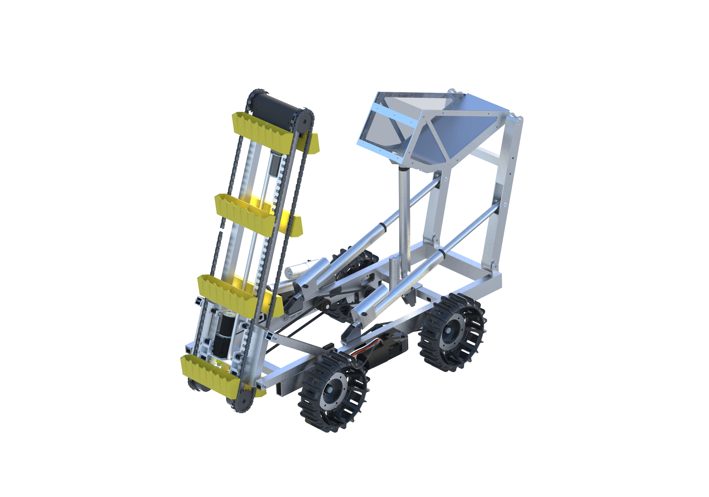
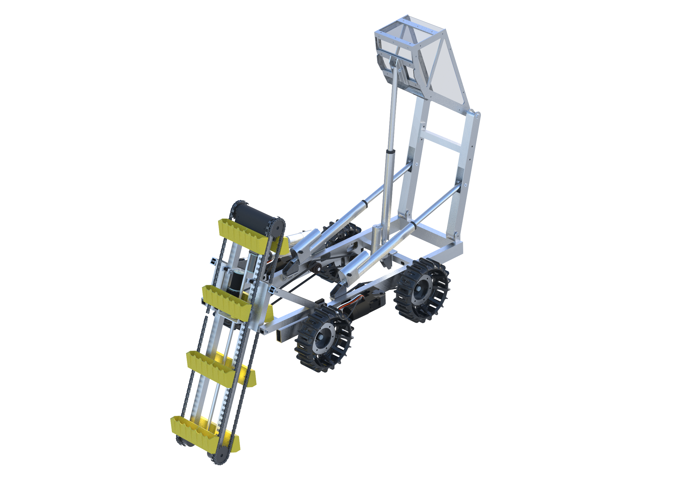
The System Integration sub team handles
the system wide CAD model. Each sub team is in control of
their respective sub models. System integration assembles
all of the sub systems into the full assembly. System
Integration also has a system of approving new changes to
any sub system. When a sub system makes a change, they fill
out a google sheet with the change they made and a path to
the file they want updated. System integration ensures that
the change that was made does not interfere with the rest of
the system, and follows the naming convention. If the file
meets the criteria, the change is accepted and fully added
to the full system. System Integration also keeps track of
the robots mass and overall dimensions to ensure the robot
meets competition requirements. The estimated mass from the
CAD and the dimensions are compared to the as-built systems
to ensure they stay within the requirements. System
Integration also keeps track of system wide and sub system
testing matrices.
Updated: October 11, 2022
